
Fareed Mohmed · Engineering
Coupling Selection Calculator
Rate · Factor · Verify
Enter your application data once: load, shafts and misalignment. The type cards, the filtered list and the recommendation update as you type, with every step shown.
Ratings are catalogue values: MISUMI Malaysia Economy series 2025 (pages 06-026, 06-027, 06-032); SKF couplings catalogue 15822 (grid, gear, laminate disc and flex tyre); and the SKF OK coupling brochure 17372 with the OKFX leaflet (oil-injection keyless couplings). MISUMI prints no service-factor table, so its factors here are the usual generic structure; SKF and OK use their own published factors. Confirm the factor for your machine, and confirm the exact part with the supplier, before ordering.
Start Here: The Selection Process
Eight steps from the application to the part number. Read this once, then use sections 01 to 03 to do it: every step below links to the place where you enter or read it. If you are new to couplings, this page is your checklist.
Define the application
Write down what the coupling must do before you pick anything. Most wrong selections start with a missing fact here.
- Machine and driver: what turns what (motor, servo, engine, gearbox)
- Power in kW and the running speed in RPM
- Duty: continuous, intermittent, or reversing
- Environment: heat, dust, water, chemicals; and the space available
Calculate the design torque
Torque from power and speed is T = 9550 × P(kW) / n(RPM), in N·m. That is the average running value. Real machines start, stall and shock, so multiply by a service factor to get the design torque: Td = T × Sf.
Check the shafts
- Diameter on both sides (they can differ)
- Shaft material, which sets how much torque the shaft itself can carry
- Shaft end: plain round, or keyed. Keyless clamp and oil-injection couplings need plain; keyed hub couplings need a keyway
Is misalignment expected?
Two shafts on two machines are never perfectly in line. Ask whether your assembly can hold them aligned and rigid.
No, both shafts sit on one stiff frame and are aligned accurately → a rigid coupling is possible. In this tool the rigid ones are the SKF OK oil-injection sleeve and flange couplings; ordinary sleeve, flange and clamp rigid couplings are not in the data.
Yes, or you are not sure → use a flexible coupling and go to step 5.
Estimate the amount of misalignment
- Angular, in degrees: the shaft axes meet at an angle
- Parallel, in mm: the axes are parallel but offset
- Axial, in mm: the shafts move in and out (thermal growth, end float)
Choose the coupling type
You do not have to pick a type first. Leave section 02 on All types and the sizing decides; the cards show how many couplings of each family pass your numbers. Use this table to understand why the survivors are what they are, or to narrow the list by need.
| Main need | Family | In this tool |
|---|---|---|
| High torque, zero backlash, precise, high speed | Disc | MISUMI single and double disc, SKF laminate disc |
| Small servo or positioning axis | Single or double disc, slit | MISUMI Economy |
| Absorb shock and vibration, tolerate misalignment | Flex tyre, grid | SKF flex tyre, SKF grid |
| Very high torque in a compact body, heavy duty | Gear | SKF gear (needs lubrication) |
| Large shaft, keyless, quick to fit and remove, shafts accurately aligned | Oil-injection rigid | SKF OK sleeve and flange |
| Cheap, simple, low misalignment (jaw, elastomer) | Jaw, elastomeric | Not in the data yet: use the Quick Check in section 04 |
| Electrical isolation | Composite or elastomer | Not in the data yet |
Check the ratings and finalise the size
This is the part the calculator does for you. A coupling stays in the list only if it passes every check:
- Rated torque ≥ design torque (with margin)
- Maximum speed ≥ running speed
- Both shaft diameters fit the bore range, and the shaft end matches (keyed or plain)
- Angular, parallel and axial misalignment are within the limits
- Torsional windup is acceptable for positioning axes
- The shaft from step 3 can carry the design torque of that coupling
Finalise and order
- Pick the material (steel, stainless, aluminium) for the environment
- Choose the supplier and exact part from the part number shown
- Check availability, cost and maintenance (lubrication, wear parts)
- Confirm with the supplier before ordering. The tool shows what it did not check
Six common mistakes
Brands that make this product
Filled gold: loaded in this tool and rated from the catalogue. Outlined gold: loaded for part numbers only, not strength-checked. Grey dashed: not loaded yet. Hover a brand for what is loaded.
 SKFrated
 SKF OKrated
 MISUMIrated
 KTRnot yet
 Rexnordnot yet
 Lovejoynot yet
 R+Wnot yet
 Rulandnot yet
 Flendernot yet
 Tsubakinot yet
 Miki Pulleynot yet
 Fennernot yet
 Voithnot yet
To use a brand that is not loaded, take the design torque Td from section 03 to that brand’s catalogue and check the rated torque, bore range, speed and misalignment the same way. The Quick Check in section 04 tests any coupling’s rated torque against your design torque.
See every hardware and brand →Brand names and logos are trademarks of their owners and are shown only to identify catalogues.
Application Data
Everything the selection needs, in one place. Change any value and the type cards and the results below update straight away. Nothing else has to be entered further down.
Choose a Coupling Type
Pick a family, or leave it on All types. The number on each card is how many couplings of that family pass every check for the application data above, so you can see at once which families can do the job. Families are grouped by supplier. The SKF grid, gear, disc and flex couplings have keyed bores, so set the shaft ends to Keyway to include them; the SKF OK oil-injection couplings are keyless, so they need Plain shaft ends. Photos are from the MISUMI and SKF catalogues.
Results & Recommendation
The data above is checked against 423 catalogue couplings from MISUMI and SKF. A coupling stays in the list only if it passes torque, speed, both shaft bores, shaft ends, misalignment and windup. Each catalogue uses its own service factor, so the “Required” column is the design torque for that coupling. The lowest-rated survivor is recommended; pick any other row to see its full working.
Steps
Quick Check of Any Other Coupling
Using a coupling from another supplier? Enter its rated torque and it is compared with the design torque Td from Application Data (section 01).
Find Coupling Type by Application
Visual Reference — All Coupling Types
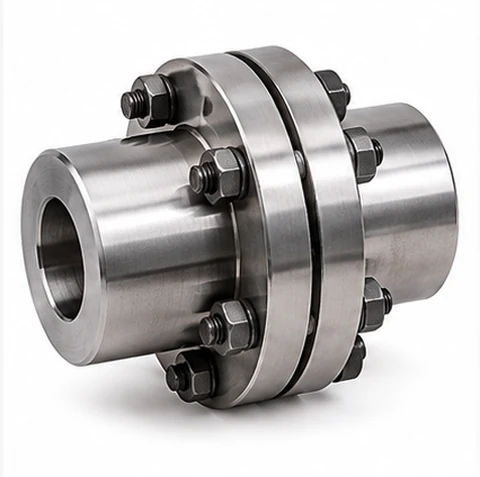
Rigid Coupling (Sleeve / Flange)
Two flanges (or a single sleeve) bolted or clamped solidly to both shaft ends, transmitting torque with essentially zero backlash or flex. Demands shafts that are already accurately aligned — any misalignment loads the shafts and bearings directly rather than being absorbed by the coupling.
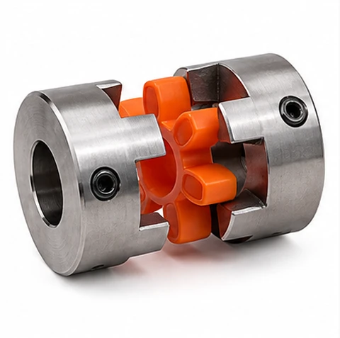
Flexible Jaw / Spider Coupling
Two claw-like hubs drive an elastomeric spider insert in compression rather than touching each other directly. The rubber or polyurethane spider absorbs shock and minor vibration and is the wear item — cheap and fast to replace without moving either shaft. The general-purpose default for pumps, fans and gearboxes.
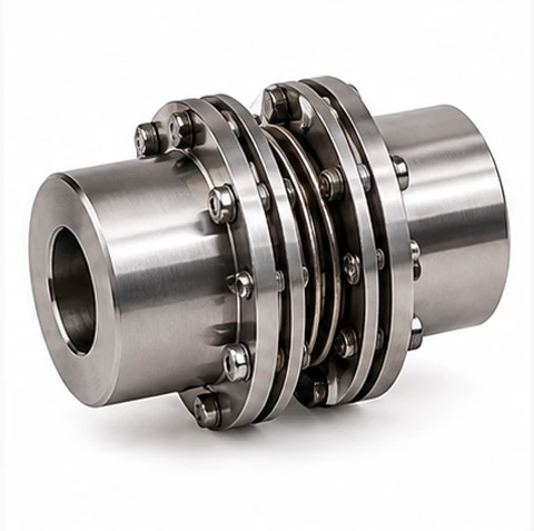
Flexible Disc / Diaphragm Coupling
A stack of thin stainless steel discs bolted alternately to each hub flexes to absorb angular, parallel and axial misalignment with no elastomer to wear out and no backlash. Runs true at high speed and holds up well to temperature extremes — common on precision drives and turbomachinery.
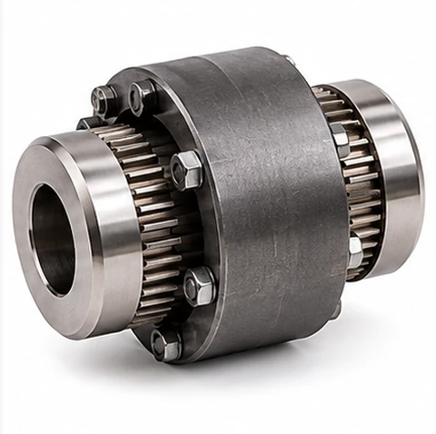
Gear Coupling
External gear teeth on each hub mesh with internal teeth in a sleeve; the teeth are crowned so they can articulate slightly to accommodate misalignment while still transmitting very high torque in a compact envelope. Needs periodic lubrication (grease or continuous oil) — the classic choice for heavy industrial drives before flexible-disc alternatives became common.
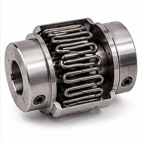
Grid (Spring) Coupling
A serpentine steel spring grid threads through slots in two opposing hub flanges, flexing to absorb shock and cushion torque reversals while still transmitting substantial torque. More rugged and heat-tolerant than an elastomer spider, at the cost of needing grease and a cover.
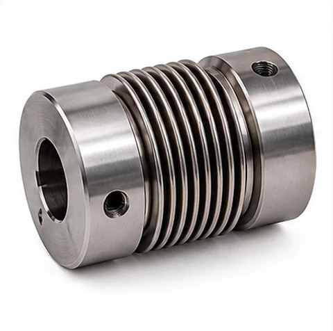
Bellows Coupling
A thin-walled metal bellows between two hubs flexes to take up misalignment with essentially zero backlash and very low added inertia — ideal where position accuracy matters more than torque capacity. Torque capacity is modest, so this is a light-duty, high-precision coupling rather than a power-transmission workhorse.
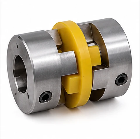
Oldham Coupling
A three-piece coupling: two hubs each with a diametrical tongue drive a floating center disc with two perpendicular slots, which slides to accommodate parallel shaft offset while transmitting torque at a constant angular velocity. Handles parallel misalignment far better than a jaw or disc coupling of similar size.
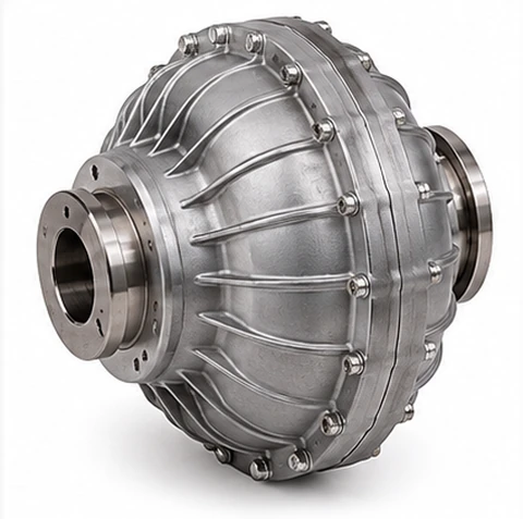
Fluid Coupling
Torque is transmitted hydrodynamically between two vaned impellers through oil, with no rigid mechanical connection at all — the coupling slips under a stall or overload rather than transmitting a damaging torque spike, and lets a motor start and come up to speed smoothly against a heavy inertial load.
Reference Tables
| Driver Type | Uniform Load (fans, centrifugal pumps, light conveyors) | Moderate Shock (reciprocating pumps, machine tools, mixers) | Heavy Shock (crushers, punch presses, reciprocating compressors) |
|---|---|---|---|
| Servo or Stepper Motor (peak torque) | 1.0 | 1.5 | 2.0 |
| Electric Motor or Turbine (smooth) | 1.0 | 1.5 | 2.5 |
| Multi-Cylinder IC Engine | 1.25 | 1.75 | 2.75 |
| Single-Cylinder IC Engine | 1.5 | 2.0 | 3.0 |
Typical service factor structure, following the pattern published across coupling and power-transmission-component catalogs — confirm the exact figure for your chosen manufacturer and duty cycle. The servo row is typical practice, applied to the motor’s peak torque.
MISUMI Economy series couplings used by the selector
| Part | Type | Length L (mm) | Allowable torque (N·m) | Max speed (rpm) | Lateral (mm) | Angular (°) | Torsional rigidity (N·m/rad) | Axial ± (mm) | Mass (g) | Bore Ø (mm) |
|---|---|---|---|---|---|---|---|---|---|---|
| E-LMCPS12 | Single disc coupling | 12.35 | 0.25 | 10000 | — | 0.5 | 266 | 0.04 | 3 | 3–5 |
| E-LMCPS16 | Single disc coupling | 17 | 0.6 | 10000 | — | 0.5 | 510 | 0.05 | 7 | 3–6 |
| E-LMCPS19 | Single disc coupling | 20 | 1 | 10000 | — | 1 | 1400 | 0.09 | 11 | 3–8 |
| E-LMCPS20 | Single disc coupling | 23 | 1 | 10000 | — | 1 | 1800 | 0.1 | 20 | 3–8 |
| E-LMCPS26 | Single disc coupling | 25.5 | 2 | 10000 | — | 1 | 3700 | 0.14 | 28 | 5–14 |
| E-LMCPS29 | Single disc coupling | 25.7 | 2.2 | 10000 | — | 1 | 3700 | 0.18 | 35 | 5–14 |
| E-LMCPS32 | Single disc coupling | 28 | 6 | 10000 | — | 1 | 5700 | 0.18 | 46 | 5–15 |
| E-LMCPS33 | Single disc coupling | 28.5 | 6 | 10000 | — | 1 | 5800 | 0.18 | 50 | 5–16 |
| E-LMCPS34 | Single disc coupling | 32 | 6 | 10000 | — | 1 | 8100 | 0.18 | 55 | 5–16 |
| E-LMCPS39 | Single disc coupling | 34.5 | 13 | 10000 | — | 1 | 18000 | 0.23 | 81 | 8–19 |
| E-LMCPS44 | Single disc coupling | 34.5 | 15 | 10000 | — | 1 | 20000 | 0.27 | 99 | 8–22 |
| E-LMCPS56 | Single disc coupling | 45 | 28 | 10000 | — | 1 | 50000 | 0.36 | 217 | 10–32 |
| E-LMCPS68 | Single disc coupling | 53 | 60 | 9000 | — | 1 | 70000 | 0.4 | 348 | 12–38 |
| E-LMCPS82 | Single disc coupling | 68 | 100 | 8000 | — | 1 | 140000 | 0.5 | 689 | 17–42 |
| E-LMCPW12 | Double disc coupling | 15.9 | 0.25 | 10000 | 0.03 | 1 | 133 | 0.08 | 3.7 | 3–5 |
| E-LMCPW16 | Double disc coupling | 23 | 0.6 | 10000 | 0.05 | 1 | 255 | 0.1 | 10 | 3–6 |
| E-LMCPW19 | Double disc coupling | 27 | 1 | 10000 | 0.1 | 1.5 | 700 | 0.18 | 14 | 3–8 |
| E-LMCPW20 | Double disc coupling | 28.8 | 1 | 10000 | 0.1 | 1.5 | 900 | 0.2 | 19 | 3–8 |
| E-LMCPW26 | Double disc coupling | 35 | 2 | 10000 | 0.15 | 1.5 | 1850 | 0.3 | 37 | 5–14 |
| E-LMCPW29 | Double disc coupling | 34.3 | 2 | 10000 | 0.15 | 1.5 | 1850 | 0.3 | 43 | 5–14 |
| E-LMCPW32 | Double disc coupling | 41 | 6 | 10000 | 0.18 | 1.5 | 2700 | 0.36 | 67 | 5–15 |
| E-LMCPW33 | Double disc coupling | 40 | 6 | 10000 | 0.2 | 1.5 | 2900 | 0.4 | 60 | 5–16 |
| E-LMCPW34 | Double disc coupling | 45 | 6 | 10000 | 0.2 | 1.5 | 4050 | 0.4 | 77 | 5–16 |
| E-LMCPW39 | Double disc coupling | 50 | 13 | 10000 | 0.24 | 1.5 | 9000 | 0.45 | 118 | 8–19 |
| E-LMCPW44 | Double disc coupling | 50 | 15 | 10000 | 0.24 | 1.5 | 10000 | 0.54 | 144 | 8–22 |
| E-LMCPW56 | Double disc coupling | 64 | 28 | 10000 | 0.27 | 1.5 | 25000 | 0.72 | 318 | 10–32 |
| E-LMCPW68 | Double disc coupling | 75 | 60 | 9000 | 0.31 | 1.5 | 35000 | 0.8 | 492 | 12–38 |
| E-LMCPW82 | Double disc coupling | 98 | 100 | 8000 | 0.55 | 1.5 | 70000 | 0.9 | 1013 | 17–42 |
| E-LMPLCN12 | Slit coupling | 18.5 | 0.4 | 10000 | 0.1 | 1.5 | 32 | 0.2 | 4.8 | 3–6 |
| E-LMPLCN16 | Slit coupling | 23 | 0.5 | 9000 | 0.1 | 1.5 | 44 | 0.2 | 9.3 | 3–8 |
| E-LMPLCN20 | Slit coupling | 26 | 1 | 7500 | 0.1 | 1.5 | 110 | 0.2 | 16.5 | 4–10 |
| E-LMPLCN25 | Slit coupling | 31 | 2 | 6000 | 0.15 | 1.5 | 162 | 0.2 | 29 | 5–12 |
| E-LMPLCN32 | Slit coupling | 41 | 4 | 4600 | 0.15 | 1.5 | 228 | 0.2 | 56 | 8–16 |
| E-LMPLCN40 | Slit coupling | 56 | 8 | 3600 | 0.2 | 1.5 | 340 | 0.2 | 131 | 10–20 |
| E-LMPLCN50 | Slit coupling | 71 | 15 | 3000 | 0.2 | 1.5 | 580 | 0.2 | 265 | 12–32 |
| E-LMPLCN63 | Slit coupling | 90 | 32 | 2200 | 0.2 | 1.5 | 840 | 0.2 | 562 | 14–40 |
Values as printed in the MISUMI Malaysia Economy series 2025 catalogue, pages 06-026, 06-027 and 06-032. Single disc couplings allow no lateral offset. A few printed moment-of-inertia values look inconsistent between neighbouring sizes and are used as printed.
SKF and SKF OK couplings used by the selector
SKF service factors by machine (grid, gear, flex and disc)
| Machine | Grid, gear, flex (tables 9, 10) | Disc (table 11) |
|---|---|---|
| Agitator, pure liquids | 1.0 | 1.0 |
| Agitator, screw, paddle or variable concentration | 1.5 | 1.5 |
| Fan or blower, centrifugal | 1.0 | 1.5 |
| Blower, lobe or vane | 1.25 | 1.5 |
| Compressor, centrifugal | 1.0 | 1.5 |
| Compressor, reciprocating, 4+ cylinders | 1.75 | 3.0 |
| Conveyor, belt, apron or chain | 1.0 | 2.0 |
| Conveyor, screw or bucket flight | 1.25 | 2.0 |
| Conveyor, reciprocating | 1.75 | 3.0 |
| Cooling tower fan | 2.0 | 2.0 |
| Crusher, ore or stone | 2.5 | 3.5 |
| Pump, centrifugal, constant speed | 1.0 | 2.0 |
| Pump, gear, rotary or vane | 1.25 | 1.5 |
| Pump, reciprocating, 3+ cylinders | 1.5 | 2.5 |
| Extruder, plastic | 1.5 | 2.0 |
| Generator, even load | 1.0 | 1.5 |
| Hammermill | 1.75 | 3.0 |
| Rotary kiln | 2.0 | 2.0 |
| Ball or rod mill | 2.0 | 2.5 |
| Machine tool, main drive | 1.5 | 2.0 |
| Machine tool, auxiliary drive | 1.0 | 1.5 |
| Concrete mixer | 1.75 | 2.0 |
| Vibrating screen | 2.5 | 3.0 |
Selected lines from SKF catalogue 15822, for an electric motor driver with standard starting torque. SKF says the factor must be increased for internal combustion engines but prints no value; the tool applies the ratio of the generic table for those drivers.
SKF OK safety factor f (Mt max ≥ f × T)
| Driver | Uniform load | Moderate shock | Heavy shock |
|---|---|---|---|
| Electric motor, turbine, servo | 2.25 | 2.5 | 2.75 |
| Multi-cylinder engine | 2.5 | 2.75 | 3.0 |
| Single-cylinder engine | 3.0 | 3.25 | 4.0 |
Upper end of each range printed in the OK brochure 17372. Mt max = π · da² · B · p · μ / (2 · 10³) in N·m with da in mm, B = da, μ = 0.14, and p = 120 N/mm² for OKC or 100 N/mm² for OKF.
| Coupling Type | Key Characteristics |
|---|---|
| Rigid Coupling (Sleeve / Flange) | No misalignment tolerance · Maximum torsional stiffness · Requires precise shaft alignment |
| Flexible Jaw / Spider Coupling | Moderate misalignment tolerance · Absorbs shock via elastomer insert · Low cost, easy to service |
| Flexible Disc / Diaphragm Coupling | Zero backlash · Handles misalignment by flexing thin metal discs · Good at high speed |
| Gear Coupling | Very high torque capacity · Some misalignment tolerance via crowned teeth · Needs lubrication |
| Grid (Spring) Coupling | Good shock absorption · Moderate misalignment tolerance · Rugged, tolerant of harsh environments |
| Bellows Coupling | Zero backlash · Very low inertia · Low torque capacity · Precision motion control |
| Oldham Coupling | Excellent parallel misalignment tolerance · Zero backlash version available · Moderate torque |
| Fluid Coupling | Smooth, slip-based start-up · Inherent overload protection · No mechanical wear item to replace |
Explanatory Notes
How the selector filters couplings
1) Nominal torque T = 9550 P / n, or the torque you enter. 2) Design torque Td = T × Sf. 3) Torque: allowable torque ≥ Td. 4) Speed: your running speed ≤ the coupling’s maximum speed. 5) Bores: both shaft diameters must be in the coupling’s catalogue bore list, and keyed ends need Ø8 or more. 6) Misalignment: your angular, parallel and axial values must each be within the catalogue allowance, and single disc couplings take no parallel offset. 7) Windup: θ = Td / torsional rigidity, shown in arc-minutes and optionally limited. Survivors are ordered by outside diameter, then length, so the first is the smallest.
What MISUMI does and does not publish
The Economy catalogue prints allowable torque, allowable angular, lateral and axial misalignment, torsional rigidity, maximum speed, inertia and mass for the disc and slit couplings only. It gives no service-factor table, no life rule and no speed derating, so those parts of the method are the standard practice described above. The Oldham, jaw and set-screw versions list dimensions and bores but no ratings in this catalogue, so they are not selectable here. The “compensation coefficient” of 1 is printed without an explanation, so the tool checks each misalignment separately and shows the combined use as a caution. Add other suppliers by extending the data table.
What SKF and OK publish, and what this tool does with it
The SKF catalogue 15822 gives rated torque, maximum speed, bore range, mass, and misalignment limits for the grid, gear, laminate disc and flex tyre couplings. Bores are given as a range, so the tool accepts any shaft diameter inside it. All of these have keyed bores. Torsional stiffness is published only for the flex tyre coupling, and inertia only for some sizes, so windup is checked only where the stiffness exists. The OK brochure gives Mt max for each size and shaft diameter; the OK couplings are rigid and keyless, so any misalignment entered will rule them out.
Service factors differ by catalogue
Grid, gear and flex couplings use SKF tables 9 and 10, disc couplings use the higher table 11, and OK couplings use the safety factor f. Choose a machine in section 01 to use the SKF values; without one the generic factor is used for SKF and MISUMI alike. The results show the design torque for each catalogue, and the shaft torsion check uses the design torque of the coupling being tested.
Assumptions made in the SKF data
Grid: the angular limit is 0.25°, the parallel value is the printed operating offset, and the axial value is the gap tolerance; sizes 1210 to 1260 are left out because no misalignment figures were found. Gear: the 1.5° angular limit comes from the catalogue summary, and parallel offset is published only up to size 70. Disc: the angular limit is 1° (W4), 0.7° (W6) or 0.5° (W8); single-pack types allow no parallel offset, and the parallel limit of double-pack types is the shortest spacer length times tan of the angular limit. Flex: the rating is the nominal torque. A “—” in a table means the source does not give the value.
Not in the data
The SKF catalogues also list chain, FRC, jaw, universal joint, floating shaft, spacer and taper-bush couplings, and single-engagement gear couplings. They are not included because their ratings are given in a different form (by size and bush, or by speed and power) and cannot be filtered the same way. Use the Quick Check in section 04 for those once you have the rated torque from SKF.
Torsional windup
A disc or slit coupling twists a little under torque. Windup θ = Td / k, with k the static torsional rigidity. Stiff disc couplings give very small angles. The slit couplings are much more compliant, so on a positioning axis the windup, or the coupling’s effect on servo tuning, may matter more than torque.
Why the service factor exists at all
Nominal torque from power and speed describes the average, steady-state condition — it says nothing about starting torque spikes, cyclic loading from a reciprocating machine, or shock from a crusher or press. The service factor inflates the design torque to cover that gap, the same way a service factor works for a chain drive, V-belt or gear reducer.
Bore and speed still need their own checks
A coupling that passes on torque alone can still fail to fit — its bore range has to cover both shaft diameters (which may differ), and every coupling has a maximum rated speed that drops as bore size increases due to balance and centrifugal stress. Confirm both against the manufacturer's selection chart once a torque-capable type is shortlisted.
Flexible couplings are not a substitute for good alignment
Even a coupling rated for several degrees of misalignment runs cooler, lasts longer and vibrates less the more accurately the shafts are aligned to begin with — the misalignment rating is a tolerance for what's left after a competent alignment job, not a design target.
Related tools
For the shaft this coupling connects to, see the Shaft Design Calculator. For the motor and gearbox on the other side of it, see the Motor & Gearbox Selector and Motor & Gearbox Output Calculator. For a servo axis specifically, the Servo Motor Sizing Calculator checks inertia matching and torque.