
Fareed Mohmed · Engineering
Motor & Gearbox Mount Selector
Select · Identify · Mount
Pick your application and find the right motor mounting type or gearbox mounting type — with a reference image for each, a full visual set, and the reasoning behind the choice.
Find Motor Mount by Application
Find Gearbox Mount by Application
Visual Reference
Motor Mounts
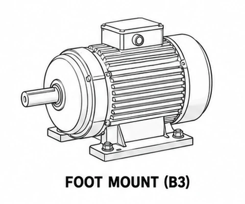
Foot Mount (B3)
Motor sits on two mounting feet, bolted flat to a base, bedplate or skid. No flange at the shaft end.
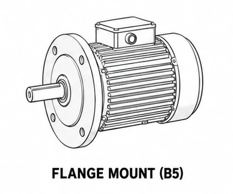
Flange Mount (B5)
A large-diameter flange with through-bolt clearance holes at the shaft end. No feet — the flange alone carries the motor.
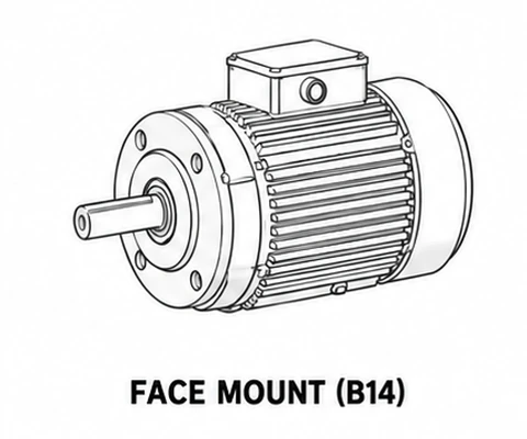
Face Mount (B14)
A smaller-diameter flange with tapped blind holes (no through-bolts) at the shaft end. Compact, no feet.
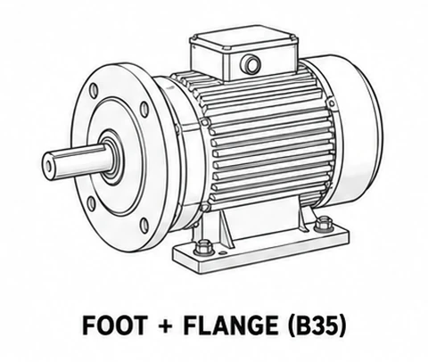
Foot + Flange (B35)
Combines both — feet on the underside for base support, plus a flange at the shaft end for alignment. Belt-and-braces mounting for demanding duty.
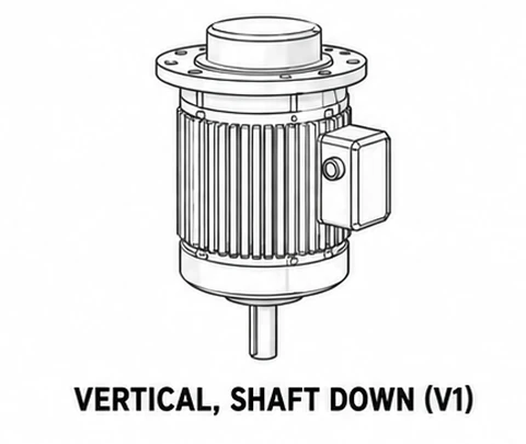
Vertical, Shaft Down (V1)
Motor stands vertically, flange-mounted at the top, with the shaft pointing straight down into the driven machine below.
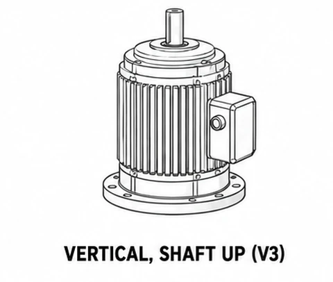
Vertical, Shaft Up (V3)
Motor stands vertically, flange-mounted at the bottom, with the shaft pointing straight up into overhead machinery.
Gearbox Mounts
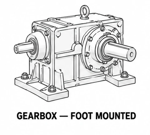
Foot Mounted
A standalone gearbox bolted to a bedplate or frame by its own feet, with input and output shafts running out to separate couplings. Both shafts carry their own bearing support.
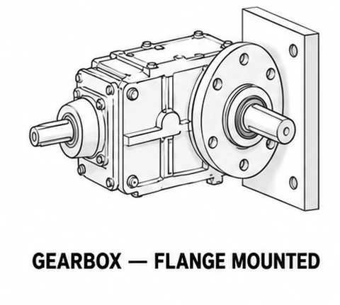
Flange Mounted
The gearbox output side bolts directly onto the driven machine's own housing through a flange — no feet, no separate coupling.
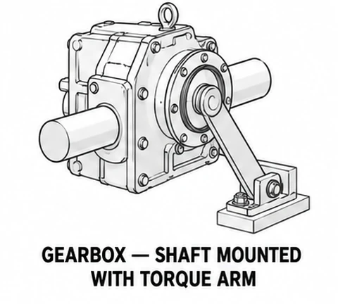
Shaft Mounted with Torque Arm
A hollow-bore gearbox slides directly over the driven shaft — no separate output shaft or coupling. A torque arm links the gearbox body to a fixed bracket to react the driving torque; the shaft itself carries the radial load. A backstop can be added to this same mount to block reverse rotation when the drive stops.
Quick-Scan Table
Motor Mounts
| Type | Key Feature | Typical Use |
|---|---|---|
| Foot Mount (B3) | Feet only, no shaft-end flange | General-purpose horizontal drive on a fixed base or skid |
| Flange Mount (B5) | Large through-hole flange, no feet | Direct coupling to a gearbox or pump through a large-diameter flange |
| Face Mount (B14) | Small tapped-hole face, no feet, compact | Compact gearmotor or small pump where radial space is tight |
| Foot + Flange (B35) | Feet AND shaft-end flange together | Heavy-duty or high-vibration drive needing both base support and flange alignment |
| Vertical, Shaft Down (V1) | Vertical, flange at top, shaft down | Vertical pump or agitator with the motor mounted above the process |
| Vertical, Shaft Up (V3) | Vertical, flange at bottom, shaft up | Drive where the shaft must point upward into overhead machinery |
Gearbox Mounts
| Type | Key Feature | Typical Use |
|---|---|---|
| Foot Mounted | Bolted to a frame by feet, both shafts coupled separately | Standalone gearbox bolted to a bedplate, shafts run to separate couplings |
| Flange Mounted | Output flange bolts straight to the driven machine | Gearbox output bolts directly onto the driven machine's housing (agitator, mixer, small conveyor head) |
| Shaft Mounted with Torque Arm | Hollow bore over driven shaft, torque reacted by arm | Gearbox mounts directly on the driven shaft — belt-conveyor pulley shaft, screw-conveyor shaft |
Explanatory Notes
Where the B3/B5/B14 codes come from
These are IEC 60034-7 mounting designations. B3 is feet-only, B5 adds a large through-bolt flange with no feet, and B14 is a smaller tapped-hole face mount — also feet-less, but lower-profile and used mainly on smaller motors and gearmotors. B35 combines B3 and B5 for drives that need both a supported base and a precisely aligned flange.
V1 vs V3 — which way is "up"?
Both are vertical, flange-mounted arrangements; the difference is which end the flange sits on. V1 has the flange at the top and the shaft pointing down into the driven equipment below. V3 flips it — flange at the bottom, shaft pointing up. Get this backwards on a drawing and the coupling simply won't line up.
What a torque arm actually does
On a shaft-mounted gearbox, the driven shaft itself carries the full radial (weight and belt-pull) load through its own bearings — the gearbox is just riding on it. The torque arm's only job is to stop the gearbox housing from spinning with the shaft; it reacts the driving torque back to a fixed point, and nothing more. Sizing the torque arm bracket for radial load is a common and costly mistake.
Backstops aren't a separate mount
A backstop (anti-reverse device) bolts onto the same shaft-mounted or foot-mounted gearbox to stop it running backward when the drive is de-energized — essential on inclined or vertical conveyors where gravity would otherwise let the load roll back. It's an accessory added to a mount, not a mounting type of its own.
Related tools
For sizing the bolts that hold a flange or foot mount in place, see Bolt Grades — Axial, Shear & Torque. For the friction behind belt or coupling contact surfaces, see Friction Coefficient Finder.