
Engineering · Design for Manufacturing · 4 of 8
DFM for Welded Structures
Can the welder reach every joint, and will the frame still be straight when the last weld cools?
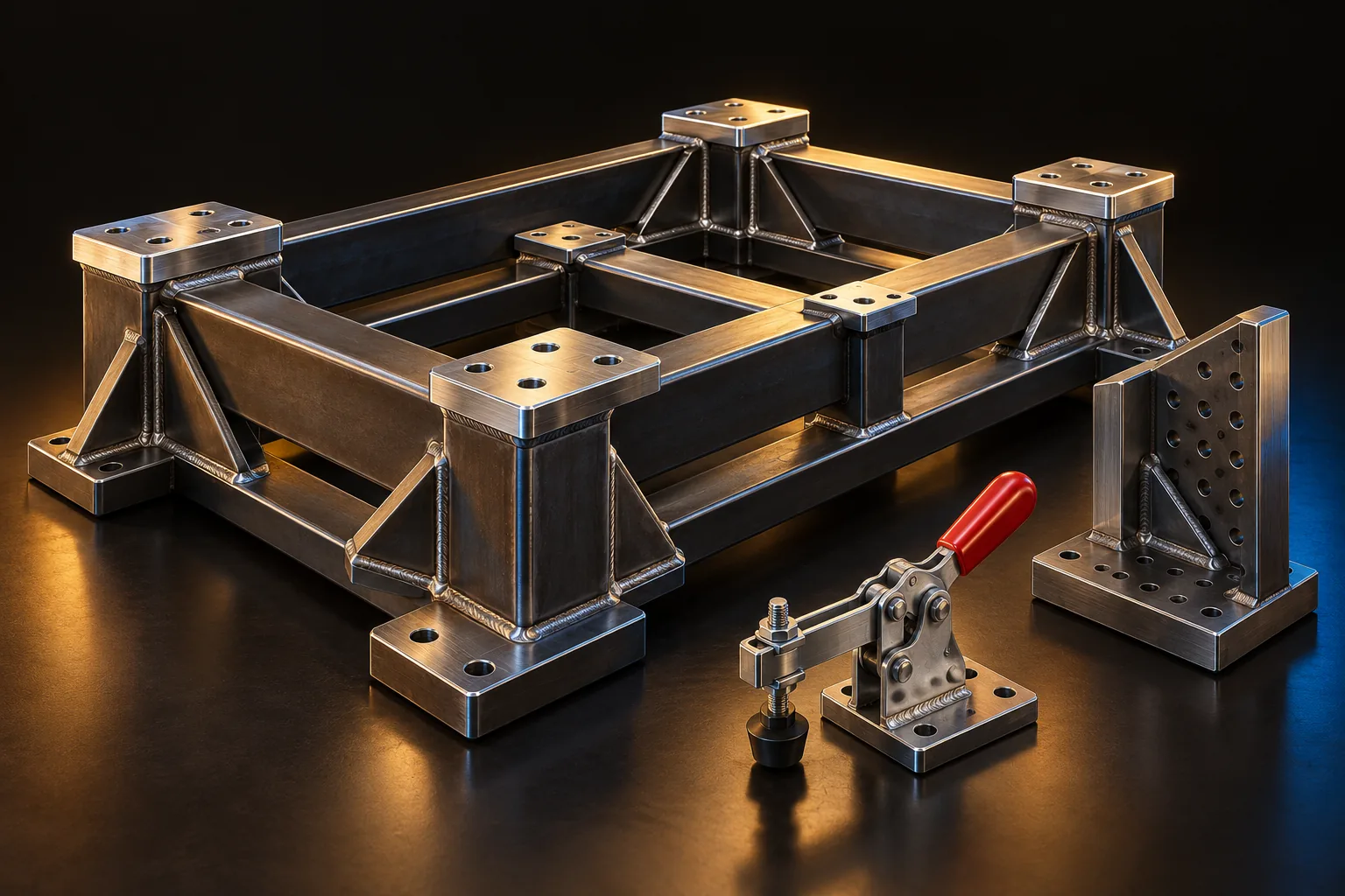
Welded frames fail DFM in predictable ways: no room for the torch, welds bigger than needed, one-sided heat, and no stock left for machining. This page covers joint choice, access clearances, a fillet weld size and capacity calculator, a builder that draws the weld symbol you describe, a heat-spreading weld order, gusset and stiffener sizing, and a stock-size calculator for frames that are machined after welding.
1Joint selection guide
| Joint | Typical use | Advantages | Limitations |
|---|---|---|---|
| Butt joint | Plates in the same plane | Strong and efficient; low material use | Needs edge preparation and good fit-up |
| Fillet joint | T-joints, lap joints, stiffeners | Simple and economical; good for most structures | Lower strength than full penetration; stress concentration at the root |
| Lap joint | Thin plates, low-strength applications | Easy to fabricate; no edge preparation | Not suitable for high strength; crevice corrosion risk |
| T-joint | Frames, brackets, stiffeners | Common and economical; easy alignment | Can be distortion prone; may need gussets for high loads |
| Corner joint | Box sections, enclosures | Simple and widely used | May need access from two sides; distortion at the corner |
| Edge joint | Thin sheet, closed sections | Good for thin materials | Limited strength; not for high-load structures |
2Weld access and clearance
If the torch or electrode cannot reach the joint, the weld will be poor or impossible. Pick a process to see the space it usually needs.
Access check
Clearances are typical minimums for the torch, nozzle or electrode holder and are shown for planning. Allow more where the welder must see the joint.
3Fillet weld size and capacity
Fillet weld calculator
allowable load per mm = throat × 0.30 × FEXX
weld metal per metre = a² / 2 × 1000 mm³
Capacity uses the AWS D1.1 allowable stress method (0.30 times electrode strength on the throat). It is an estimate to size a weld, not a design check; confirm the base metal and use your governing code (AWS D1.1, EN 1993-1-8, IS 800).
Continuous or intermittent weld
Intermittent welds cut weld metal, heat input and distortion. They are suited to non-critical joints. Use continuous welds where strength, sealing or fatigue life needs them.
| Plate thickness t | Typical shop leg range |
|---|---|
| up to 3 mm | 2 to 3 mm |
| over 3 to 6 mm | 3 to 5 mm |
| over 6 to 12 mm | 4 to 6 mm |
| over 12 mm | 5 to 8 mm |
The shop range is the common choice for fillets sized by plate thickness. The AWS D1.1 minimum (3, 5, 6 and 8 mm by thicker plate) applies to structural steel 3 mm and over; sheet steel below 3 mm falls under AWS D1.3.
4Weld symbols: build one
Weld symbol builder
Reading rules: the arrow points to the joint. Weld on the arrow side goes below the reference line, other side above. Size sits left of the symbol and length-pitch to its right. The circle at the arrow joint means all around, the flag means field weld, and the tail holds a process note.
5Distortion and how to reduce it
Welding shrinks the metal as it cools, so heat must be balanced. Common causes: uneven heat input, asymmetric weld sequence, oversize welds, rigid restraint, thin plates with long welds, and high interpass temperature.
Do
- Use balanced and symmetrical welds.
- Use intermittent welds where possible.
- Use a sequence such as skip or back-step welding.
- Minimise weld size to the strength needed.
- Use stiffeners and gussets, proper fixtures and clamps.
- Use heat sinks for thin sections; consider pre-set (camber) for critical parts.
Avoid
- Welding one side only and all at once.
- Oversize welds that add shrinkage with no strength gain.
- Starting without fixtures and clamps.
Heat-spreading weld order
6Gussets and stiffeners
Gusset and stiffener size
Do
- Use gussets at high-stress locations and weld both sides.
- Use stiffeners to stiffen panels and frames.
- Round or cut the corners to avoid sharp stress points.
Avoid
- Too-small gussets that do nothing.
- Sharp corners that concentrate stress.
The thickness range and spacing are common shop practice. Check stiffness and buckling for the real loads (the Structural Frame Analysis tool on this site includes base-plate and gusset checks).
7Post-weld machining allowance
Weld first, machine later, and leave stock where accuracy matters.
| Surface | Typical allowance |
|---|---|
| Machined flat surface | 1 to 3 mm |
| Machined hole (re-bore) | 0.5 to 1 mm |
| Side face (milling) | 1 to 3 mm |
| Top surface (milling) | 1 to 3 mm |
| Datum surface | 1 to 3 mm |
Weld frame stock size
8Design details and good practice
Avoid sharp internal corners
Use generous radii and fillets.
Use standard sections
RHS, SHS, angles and plates in stock sizes.
Keep welds away from precision areas
Heat will distort machined or ground faces.
Use back-to-back welds for symmetry
Balance shrinkage on both sides.
Avoid unnecessary welds
Every weld costs time and adds distortion.
Provide drainage and vent holes
Closed sections need a way for fluids and gas out (galvanising especially).
Design for inspection
Leave access to see and test every weld.
Provide rigid fixturing
Parts must be held in position for the whole weld.
9Try it: DFM checklist for welded structures
Weld DFM scorecard
Remember
- Use simple joints and standard sections.
- Leave weld access; check clearance for the process.
- Right-size the weld: bigger is not stronger past the plate thickness.
- Balance heat, fixture well, and weld before final machining.
- Boothroyd, Dewhurst and Knight, Product Design for Manufacture and Assembly (CRC Press), for the DFM and DFA method.
- Machinery’s Handbook (Industrial Press), for machining, sheet metal and welding practice.
- AWS D1.1 Structural Welding Code, Steel: minimum fillet weld size (Table 5.8) and allowable stress on fillet welds (Table 2.3); AWS D1.3 for sheet steel; AWS A2.4 and ISO 2553 for weld symbols.
Capacity figures are an estimate for sizing, using the AWS allowable stress method on the weld throat. They are not a substitute for a code design check by a qualified engineer.